| |
|
|
CONTROLLER AREA NETWORK (CAN BUS)USES OF CANController Area Network (CAN) connects multiple TDS2020F and TDS9092 computers for distributed real-time control applications.
For more about CAN and the J1939 Automotive bus click here.
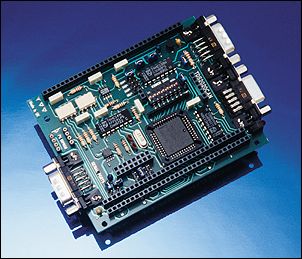
CAN adapter The TDS2020CAN board goes under the computer to form a CAN node. Use it to
q request temperature or any other sensor readings from remote equipment q control relays and lamps in a distant machine q display messages far away from the source q change parameters of machines from an office environment q synchronise instruments q collect management information from the shop floor q gather data from data loggers q intelligently connect a microphone to a set of remote loudspeakers.
The Controller Area Network data rate can be from 10kbit/s to 1Mbit/s giving recommended distances of 40 to 1000 metres over two twisted pairs, one for the data, the other to carry power and ground. Up to 110 nodes may be connected. FAST START GUIDE
1.
Set links on two TDS2020CAN boards: 2. Set the DIL switch on each board to the required node number 0 to 127. The actual value is unimportant, providing they are different�we suggest 2 and 3. 3. Connect together two nodes, each consisting of a TDS2020CAN with either a TDS2020F or TDS9092 computer. Use a cable with two twisted pairs, connecting pins 2 & 7, and 3 & 9, having a female connector at one end and a male at the other. Leave the other two CAN connectors open. 4. Power the system from one node: c32=Gnd, a32=+7 to 13V. 5. Connect a PC running TDS-PC for Windows to each node in turn. Ensure that you get the �ok� on pressing return. 6. Compile file #CANBUS.TDS on each TDS2020F node and _CANBUS.TDS on each TDS9092 node. 7. Type CANTEST and return on each computer in turn. An incrementing number is transmitted which all connected and initialised nodes will receive and display. Verify that you see the message when you change the PC plug to the other node. Stop the test with any key (ctrl+C on TDS9092). 8. Type ROLLCALL and return on each computer in turn. A memory transfer is made to all of the 128 possible nodes and responding initialised node numbers are displayed. In this case, just the identity of the other node should show.
Use the words @CAN !CAN to fetch (upload) or store (download) data from, or to, the remote CAN node. For instance:
q
with two connected TDS2020F nodes: q
with two connected TDS9092 nodes:
If the address at either end is 32-bit, perhaps in an attached PCMCIA RAM card or 512k memory chip, use E@CAN and E!CAN . It is important to ensure that status variable UPSTATUS or DOWNSTATUS is clear before initiating a transfer, otherwise the request will be ignored. You can reinitialise the hardware with 250 0 CANINIT at each computer. HARDWARECAN NETWORKController Area Network is a bus operating at RS485 levels, 0V and +5V in push-pull to give common mode immunity. Instead of being character based, it sends messages of up to eight bytes. Each of these frames has an identifier and any node with a matching identifier will receive the message. The TDS2020CAN board is based on the Intel 82527 CAN controller IC and Philips 82C250 CAN bus drivers. Each node can be either a TDS2020F + TDS2020CAN or TDS9092 + TDS2020CAN combination. The number of nodes which the network can support depends on cable lengths and bit rate, but the CAN bus driver chips are specified for at least 110 nodes. The nodes are daisy-chained, the male and female CAN connectors being internally connected. Terminating resistors on the board are connected to the bus on the two end nodes by making a link, the maximum recommended network length between the terminations is 1000m. Up to four TDS2020CAN boards can attach to one TDS2020F or TDS9092 computer, enabling a node to also act a repeater to a second CAN network. The network needs a minimum of a twisted pair, a ground reference being provided locally at each end. However, typically a twin twisted pair cable will be used, the second carrying power. CIRCUIT DIAGRAM
TDS2020CAN circuit diagram POWER SUPPLYA second pair in the CAN network cable enables one of the following:
q Use of the built-in opto-isolation, power being supplied to the whole CAN side of the system through the other two wires from a separate +7 to 13V supply. q Power supplied to the network from one TDS2020F �master� CAN node, the built-in opto-isolation being used at all the others. q Power supplied from one CAN node to all the remote computers by making links between the CAN and computer sides of the circuitry, giving only one power supply entry point to the network.
A single supply of +6V to 16V will power TDS2020F and TDS9092 computers on the network. Note that if you want compliance with the Computers in Automation (CiA) specification this should be limited to +7 to 13V over the network. The current consumption of the TDS2020CAN board is typically:
DIMENSIONSThe TDS2020CAN plugs underneath a TDS2020F or TDS9092 computer, adding 13mm to the overall height. The board size is 100 x 80mm. All pins from the top computer board are reproduced below the CAN board. CONNECTORSThe hardware of the TDS2020CAN conforms to the CiA Standard 102 version 2.0, which in turn is based on ISO 11898. Each CAN node has a 9-pin D-plug and a D-socket connected together on the board. They are also connected, via CAN bus driver/receiver chips and high speed opto-isolators, to the CAN controller chip. CAN nodes are daisy-chained together and 120-ohm terminating resistors join the two wires via link 11 on the two end nodes. CAN bus connections are:
The TDS2020CAN has a second 9-pin D-plug carrying the two serial RS232 ports of the attached computer:
BIT RATEThe bit rate used on the network determines the maximum total length from one terminating node to the other. The default baud rate set in support files is 250kbit/s. Specified bit rates, all selectable by software, are:
LINKSThe default links on shipment are 4, 7, 8 ,11 and x400.
� On TDS9092 make link 3 to select IRQ2
The last four links select the base address of the 82527 CAN chip. Each TDS2020CAN board occupies 256 bytes (hex 100) of memory space. SOFTWARE OVERVIEWOn TDS2020CAN, every node has up to 15 channels, each with its own identifier. The identifiers are dynamic, not fixed, so software can update a system configuration. For instance, channel one may be allocated to be the only channel in each node for transmitting information and it can have a unique code. The other 14 channels may be receivers and at any time be looking out for messages with matching identifiers from up to 14 other nodes. There are many ways of using these facilities. Library files #CANBUS.TDS (for TDS2020F) and _CANBUS.TDS (for TDS9092) cover most common requirements, providing functions for transmitting messages and receiving them under interrupt. These give facilities for transferring a block of memory from one computer to another over the network. This is a very versatile arrangement. Since this can be a message string for display on an LCD, a set of variables or data to be output remotely, it may be the only function you ever need. The CAN Application Layer specification by the CAN in Automation International Users and Manufacturers� Group (CiA) has been used as far as possible but the implementation is only partial. Once the memory transfer is initiated the foreground program proceeds. Continue updating a display, for example, while data is interchanged between nodes under interrupt. Alternatively you are free to use the CAN bus facilities to communicate in the most efficient way for the application at a low level, yet still using supplied routines. Files #CANPRIM.TDS (for TDS2020F) and _CANPRIM.TDS (for TDS9092) provide procedures with which you can do anything that is possible with the CAN bus hardware. The approach has been to make the details of the Intel 82527 CAN bus chip amenable, without hiding the CAN bus details. HIGH LEVEL CiA PROTOCOLOVERVIEWFile #CANPRIM.TDS provides low-level routines. #CANBUS.TDS builds on top of this a method of exchanging arbitrary-sized blocks of memory between any two CAN nodes. The data sent from one CAN node to another may be anything, for instance:
q Two bytes representing the value of a variable. q Set of 16-bit words representing the values in an array or collection of variables. q Text string for remote display. q Byte representing events such as switch closures to be notified to a remote node q Byte representing logic levels to be output at a distant place. q Digitised analog data, such as speech or sensor levels, to be reconstituted into analog remotely.
Here are some examples. Only the first three�16-bit transfers�are relevant to TDS9092:
COUNTER 2 65 COUNTER !CAN
S� The alarm is sounding� 77 $F000 !CAN
$FF8E 1 126 READING 1+ @CAN
HEX E0000. 20000. 34 100000. E@CAN DEFINITIONSThe Forth words which accomplish this transfer are E!CAN and E@CAN to send and receive data packets respectively. They use 32-bit addresses so for convenience 16-bit versions !CAN and @CAN are also defined. There is no need to understand anything about CAN bus in order to use it effectively with these procedures. High-level CAN procedures used by application programs are summarised here. Only the 16-bit versions are available on the TDS9092 computer.
@CAN ( addr1, u, node, addr2 � ) Fetch data from remote node, pronounced �fetch-CAN�. The stack parameters are: On entry: On exit:
!CAN ( addr1, u, node, addr2 � ) Send data to remote node, pronounced �store-CAN�. The stack parameters are: On entry: On exit:
E@CAN ( d-addr1, ud, node, d-addr2 � ) Fetch data from remote node, pronounced �e-fetch-CAN�. The stack parameters are: On entry: On exit:
E!CAN ( d-addr1, ud, node, d-addr2 � ) Send data to remote node, pronounced �e-store-CAN�. The stack parameters are: On entry:
On exit: PROGRESS INDICATIONIt is important to make sure the relevant status variable is clear before sending or receiving data over the CAN bus. UPSTATUS is used when collecting data from a remote computer and DOWNSTATUS when sending. The variable might not be zero for either of two reasons:
q The last collection or sending of data was unsuccessful. q CAN data transfer is currently in progress under interrupt.
If the relevant status variable is not zero a new request will be ignored. Values are to be interpreted as follows:
IDENTIFIERSIdentifiers are used to match client (node starting a request) with server (node responding to a request). For messages to pass from one to the other in either direction the identifiers have to be equal. To be compatible with CAN chips using 11-bit identifiers, only bits 28 to 18 of the extended frame are used in the high-level memory transfer protocol. 24-bit identifiers are available when using only the low-level routines in #CANPRIM.TDS. Identifiers are called COB-IDs in the CiA specification, they reside in the Arbitration Registers of the Intel 82527 CAN chip. The word IDENTIFIERS sets up message objects 7 to 12 with identifiers based on the setting of the DIL switch. Identifiers allocated start at 881, the offset from this being 6x the switch setting. Since there are 128 possible switch settings, the identifiers occupy 881 to 1648 inclusive. This leaves a parallel set of identifiers 1 to 768 at a higher CAN priority for special application-dependent needs. For the same reason, the message objects 7 to 12 chosen leave 1 to 6 free because they are hard-wired to a higher priority in the 82527 CAN chip. This table shows the 11-bit identifier settings, all in decimal, which will be used for the switch settings (node numbers) chosen:
MESSAGE OBJECTSThe 6 message objects used in the high-level protocol for exchanging data are allocated as follows, they use the Multiplexed Domain Protocol of the CiA specification:
TIMINGThe CAN bus operates at 10 to 1,000kbit/s, set by one of the parameters of INITCAN which you execute when power is applied to the board (or CANBAUD for the low-level procedures). This is the hardware speed, but the CAN bus has overheads resulting in lower data-transfer speeds including:
q address information in the data packets, q the complex handshaken protocol of the CiA specification, q the need to swap tasks and execute high-level code in both the send and receive nodes every 7 data bytes.
The memory transfer protocol is handled almost entirely under interrupt so the foreground program is hardly delayed at all. In fact only the client node (the one which starts the process) foreground software is involved. The server operates entirely under interrupt and its foreground program is unaware of the transfer. These are measurements made between two TDS2020F based CAN nodes with the program in external Flash-EEPROM.
Notes: q There was no activity from other nodes at the time. q The Forth word being timed was !CAN which transfers blocks of memory from one node to another. q The CiA protocol transfers seven bytes at a time so results can appear strange. q Much greater speeds can be achieved without using the CiA protocol. LOW LEVEL SOFTWAREOVERVIEWFile #CANPRIM.TDS provides primitives with which you can do anything that is possible with the Controller Area Network (CAN) hardware. For speed, the key parts are written in assembler code but packaged as Forth words for use in higher layers. CAN messages are received under interrupt so that foreground jobs can continue at the same time.
For specialist applications use this file only. Otherwise build on top of it with:
q #CANBUS.TDS to provide a high-level method of exchanging arbitary-sized blocks of data between any two CAN nodes. q #CAN-SER.TDS for CAN bus and serial port two-way communication, also it gives interactive Forth via the CAN bus. q #CANAUTO.TDS J1939 automotive CAN bus monitor with PCMCIA or Compact Flash data logging and serial output.
Using #CANPRIM.TDS, transmission takes 83µs to send 8 bytes and 43µs to send 1 byte, but effective transmission speed may be limited by the bus. When sending 8 bytes the fastest loop time is:
q At 1000 kbaud: 280µs, effective rate: 229 kbits/s q At 250 kbaud: 616µs, effective rate: 104 kbits/s q At 20 kbaud: 5562µs, effective rate: 11.5 kbits/s
CAN message receipt takes about 200µs plus the execution time of the word you define that should be run on receipt.
For full details of the 83527 CAN controller chip at a register level, see the Intel publication �82527 Serial Communications Controller Architectural Overview�, Intel reference 272410-002. Comments in the source code and this documentation sometimes use its terminology. A copy is on the CD in the \essentials\CAN folder, along with a datasheet for the chip. Application code determines the actual function of each 82527 message object by defining routines and placing the execution tokens into a pre-defined table ACTIONS . This table can be updated at any time, even �on the fly� if necessary. It is initially set to null operation apart from clearing down any interrupt or signal flags. The table ACTIONS mimics the interrupt list (page 20 of Intel booklet). On arrival of a message for this node, the 82527 generates an interrupt. It may be assigned to any of four interrupt sources IRQ1 or the Input Capture of Timers 1, 2 or 3 via links 3 to 6 (IRQ2 via link 3 on TDS9092). On delivery, the board and this software are configured to use the Input Capture of Timer 3 as the interrupt source. The message object causing the interrupt is encoded in the interrupt register (pages 19 & 20 of Intel booklet). Although there may be more than one interrupt pending, only the highest priority one (the lowest value in the interrupt register) is presented. The routine CAN-INTERRUPT is entered which clears the interrupt source in the CAN chip and then the interrupt caused in the computer. The appropriate action for this interrupt is then extracted from the ACTIONS table and executed. Before returning, the procedure checks if clearing this interrupt uncovered another one since multiple message objects might have received messages. ACTIONS ARRAYACTIONS is the start address of an array of interrupt actions for each message object. ACTION-CAN is used to fill a location in the array. The array consists of 16 Forth word execution tokens. It is used as a look-up table to determine the action needed for each value, from 1 to 16, of the interrupt register INTREG . This table shows the correspondence:
NON-VOLATILE MEMORYAn empty socket on the TDS2020CAN adapter can hold an 8-pin Flash or EEPROM chip. The chip is on the I2C bus of the TDS2020F; use chip address $52 with the words provided in the appropriate file. It could be used for
q remote data collection, the information being forwarded over the CAN bus only when the memory is full, q extended characterisation of the CAN node, for instance to hold a name for the node.
See ON-BOARD NON-VOLATILE MEMORY, page 257, for more information. APPLICABLE STANDARDSThe �CMS multiplexed domain protocol� defined in the CAN in Automation (CiA) CAN Application Layer is used to accomplish the data transfers. Some names in comments of definitions come from this specification or the Intel 82527 Architectural Overview.
q
CAN in Automation (CiA) International Users and Manufacturers�
Group e.V. Tel. +49-9131-69086-0, fax +49-9131-69086-79, q
Intel Inc. In USA: tel. 800-538-3373, in UK: tel. +44-1793-431-155, ORDERING INFORMATIONThe TDS2020CAN adapter comes in two versions:
q TDS2020CAN-PIN to place under a TDS2020F-PIN or TDS9092-PIN computer to form a sandwich. q TDS2020CAN-PLUG to put in a rack alongside a TDS2020F-PLUG or TDS9092-PLUG computer, the two being connected by a backplane.
To make a trial CAN network we suggest:
q Two TDS2020F or TDS9092-PIN computers q Two TDS2020CAN-PIN adapters q One CANCABLE1M one metre cable
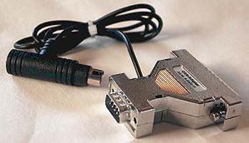
You will also need chips to hold the compiled code in the computers, for example two EEPROM32K devices for TDS2020F. CAN cables to connect nodes are also supplied, or you can make up your own. They have a 9-pin D-plug on one end and a 9-pin D-socket on the other. The length is specified in the part number, as in the example. CAN BUS TO PC INTERFACEEXTERNAL ADAPTERThe order code PC-CAN-PAR is for a small intelligent interface between PCs and a CAN network. It connects to the Parallel Printer Port of the host PC.
PC-CAN-PAR PC parallel port to CAN adapter A communication library (32 bit drivers for Windows 95/98/NT4/2000/XP) including Visual Basic sample program sources (bus monitoring program) is provided. Its small size makes it the ideal solution for connecting PCs, especially notebooks, to the network. The adapter may use an external power supply (+5 to 24V), the power can be supplied via the CAN bus connector or it may be taken directly from a PS/2 keyboard connector.
q Package includes FULL CAN Adapter, floppy disk 3.5" containing 32 bit Drivers for MS Windows 95/98/NT/2000/XP, sample application program q 32-bit drivers q Transfer rate up to 1Mbit/s q Power supply 5-24V via CAN bus or in-line with PS/2 keyboard connector q Uses Intel AN82527 CAN chip (like TDS2020F CAN adapter)
The sample program provided on the disk (source code included) allows tracing of (all or selected) activities on the network. CAN messages can be defined and transmitted. The registers of the CAN Chip can be accessed and manipulated directly. EXTERNAL CAN NODEAnother way to communicate between the CAN bus and a PC is to have a TDS2020F or TDS9092 CAN node near to the PC. Connect a serial port on the PC using the file #CAN-SER.TDS for CAN bus to RS232 intercommunication. |
 |
|