| |
||
USB INPUT AND OUTPUTSUMMARYConnect this module externally to a TDS2020F card computer to give it a USB interface to a PC. It allows faster data transfers both into and out of the TDS2020F so is particularly useful in data collection applications.
q Move bulk data from a Flash card through the USB adapter to a PC q Load a Flash card with a database from a PC though the USB adapter. q Interface into any finished application through the USB port. q Use of interactive Forth over the USB bus. q Compile over the USB port. If you want to power up with interactive Forth on the USB you must put the USB driver in the microprocessor as a Part 1 program. q Support software provided.
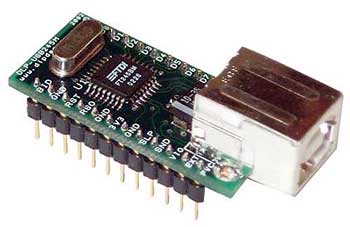
DLP-USB245M parallel to USB interface module, USB INTERFACE OPERATIONThe USB245M module is similar to a 24-pin dual-in-line IC and will plug into and IC socket. You connect the socket pins to the TDS2020F and a USB cable (type A to B) from the module to the PC. The file #usb.tds gives the TDS2020F the ability to talk to the module. To make the module communicate at its other side with a PC you install drivers in the PC. These make the module look like another COM port, say COM6. Any PC software can now use that port number to access the TDS2020F. For instance you can use TDS-PC for Windows, HyperTerminal or a program you write yourself in VB or C. At power-up the TDS2020F talks to its serial port 1 so initially you can't address it from the USB port. The support file must be compiled to do that. Once it is in place you can type USBFORTH to make further compilation over the USB link. Inclusion of file #usb.tds in an application will make it permanent so that a finished instrument can power up with USB communication, either for interactive Forth use or for data transfer between the TDS2020F and the PC. Likewise if you include the file in a Part 1 application blown into the H8/532 microprocessor the rest of the Part 2 development can take place over the USB bus. Facilities provided by this file #usb.tds include:
q USB2WAY gives two-way communication between the USB bus and a serial port. q USBFORTH redirects interactive Forth to the USB bus and 1FORTH typed on the USB input puts it back again to serial port 1. q The structure <USB ...usb i/o... USB> inside a definition temporarily redirects all input/output to the USB bus. The bracketing words must both be present and matching within a single Forth word.
For instance, to send all the data from a Flash card to the USB port make up a word USBSQUIRT like this (depends on #doshd.tds for Flash handling)
: USBSQUIRT ( -- ) <USB SQUIRT USB> ; INSTRUCTIONS FOR USE1. Connect a USB245M module externally to a TDS2020F computer. The pin connections are shown in a following section. 2. Connect the TDS2020F through serial port 1 to your PC in the normal way and switch on the TDS2020F. 3. Open TDS-PC for Windows and check that you are interactive with the TDS2020F. 4. Put the TDS Compact Disk in your computer ready for installation of drivers for the USB245M. 5. Connect a USB cable (type A to B) between your PC and the USB245M module. 6. The Add Hardware Wizard should start. If the driver files are not found automatically, choose 'search for a suitable driver' and on the next screen choose 'specify a location'. On the next screen navigate to the FTDI folder on the CD. Installation should then follow smoothly. You will see that the Add Hardware Wizard is called twice, once for the USB245M itself and again for the USB COM port. The operating system will choose the appropriate pair of .inf files from the FTDI directory on the CD. From Device Manager find the com port number that has been allocated to the USB connection. You can find Device Manager from the sequence 'Start button, Control panel, System, Hardware tab, Device manager'. There is more information on this installation in pdf files in the FTDI directory. 7. Assuming that you are using a single PC for both the serial development interface to the TDS2020F and the USB interface, open HyperTerminal by following this sequence: 'Start button, All programs, Accessories, Communications, HyperTerminal'. Give the new connection a name and on the next screen pull down the 'connect using' combo box so that you can select the com port installed at step 6. In the port settings box change the settings to 115200 baud and no flow control. HyperTerminal is now ready to communicate with the TDS2020F. 8. From TDS-PC for Windows compile th the support file #usb.tds. 9. Finally test operation by typing USB2WAY (return). Any key typed in HyperTerminal now travels over the USB bus to the TDS2020F and is output to TDS-PC for Windows on serial port 1. The reverse is also true and you should have two-way communication. Get out of the test with ctrl/c. RESOURCES USEDPort 9 bits 2, 3 and 4 are used for control of the USB module. If you need these for D/A output or something else edit the CONSTANTS section in the file #usb.tds. For output from the TDS2020F to the PC the chip select signal CS81B0* is needed. If you will use the in-built keypad words NEWKEY or INKEY to drive a matrix keyboard you should decode another address with an additional external chip. The chip select signal you produce should go low only during the second part of the synchronised E clock cycle, the time when E is high. This means that the E signal must go into the decoding chip. Edit the new write address into the CONSTANTS section. For input from the PC to the TDS2020F the chip select signal CS81A0* is needed. If you will use this for another purpose, for example as a graphics display chip select, you should use alternate signals CS8180* or CS8190* or decode another address with an additional external chip. In this case the E signal need not (but can) go into the decoding chip. Edit the new read address into the CONSTANTS section. No other ports are used because the module hangs on the TDS2020F data bus. PIN CONNECTIONSThe DLP-USB245M datasheet is here for reference.
TIMINGSWe have timed transfers over the USB at the equivalent of between 110k baud and 175k baud using a virtual com port on the PC, depending on the particular test and speed of PC. In datalogging applications a Flash card can be copied to the PC at a rate of just over a minute per megabyte. Although data transfer by USB is an order of magnitude faster than the serial port, compilation speed improves only by 25% or so (but more on a slow PC) because the main limitation is the compiler on the TDS2020F, not the serial link. |
|||||||||||||||||||||||||||||||||||||||||||||||||||||||||
 |
|