| |
|
|
INTERRUPTSDEFINITIONS
q See INTERRUPT JUMP TABLE, page 170, for interrupt addresses q See INTERRUPT MULTITASKING, page 182, for repetitive interrupts q See H8/500 STRUCTURED FORTH ASSEMBLER, page 150, for assembler. AVOID INTERRUPTS WHEN POSSIBLEInexperienced real-time programmers often think that interrupts are essential, for example that an interrupt should always occur every time a particular event happens. This might be necessary but interrupts are more difficult to debug and mutual interference of different interrupts due to inadequate safeguards may only show up problems in your program years after the design. The advice to someone who is still learning real-time design must be to avoid all interrupts on whatever microprocessor. In some safety-critical applications, for example in certain railway uses, interrupts in programs are banned. Each job is different, however, and there are occasions where you must use interrupts. Having said that, the TDS2020F has 43 possible interrupts and they can all be used in one program if you wish! A program written in Assembler or high-level Forth can be tied to each. TDS2020F is particularly suitable for applications where interrupts are necessary and the next section may help you decide. EXAMPLE PROBLEMThis example demonstrates how an application apparently needing interrupts could probably be done better without them. A particular application needs a keyboard and LCD display. The system counts items on a production line conveyor belt and shows the number on the LCD. One solution is to have a main program for the LCD and keyboard and to interrupt the TDS2020F when an item arrives. The essence of the main program is:
: DISPLAY ( - ) \ Number of items to LCD #ITEMS @ \ get number of items ['] LCDEMIT 'EMIT ! \ revector EMIT to LCD 0AT 6 U.R \ show qty on LCD ['] <EMIT> 'EMIT ! ; \ back to serial port : WORK ( - ) \ Word executed at power-up INITIALISE BEGIN BEGIN DISPLAY NEWKEY ?DUP UNTIL PROCESSKEY AGAIN ;
Here we will not concern ourselves with the detail of PROCESSKEY or INITIALISE . Perhaps a certain key will cause the number of items counted in the variable #ITEMS to be sent down the serial link to another computer for example. The interrupt program is:
: TALLY ( - ) 1 #ITEMS +! RETURN;
This increments a variable #ITEMS when an external interrupt arrives and then we return from interrupt back to the main program WORK shown above. It remains to establish WORK as the main, or foreground, task and TALLY as the background task. The former is done as shown in STAND-ALONE SYSTEMS, page 232, using the supplied word SET and the latter, of concern to us here, is done with ASSIGN . Include the following, most conveniently done at the end of the program listing:
-63 +ORIGIN ASSIGN TALLY \ Associates TALLY with the \ interrupt IRQ0 at this address
The address for IRQ0 -63 +ORIGIN is taken from the Interrupt Jump Table. Having seen the outline of how to approach this counting problem using interrupts, note that it might have been possible to do it without them:
: TALLY ( - ) ?ITEM IF 1 #ITEMS +! THEN ; : WORK ( - ) \ Word executed at power-up INITIALISE BEGIN BEGIN DISPLAY TALLY NEWKEY ?DUP UNTIL PROCESSKEY AGAIN ;
This works because the program spends most of its time in the middle BEGIN . UNTIL loop. As long as PROCESSKEY does not take longer than the time between items arriving on the conveyor the second, non-interrupt, solution would be the better one. The BEGIN . UNTIL can be called a 'flash around loop' because you design it to be as quick as possible, diverting to do other functions, or part of a function, for only short times. Interrupts can be written either in assembly language or, as above, in high-level Forth. These are considered in turn later. NON-MASKABLE INTERRUPT
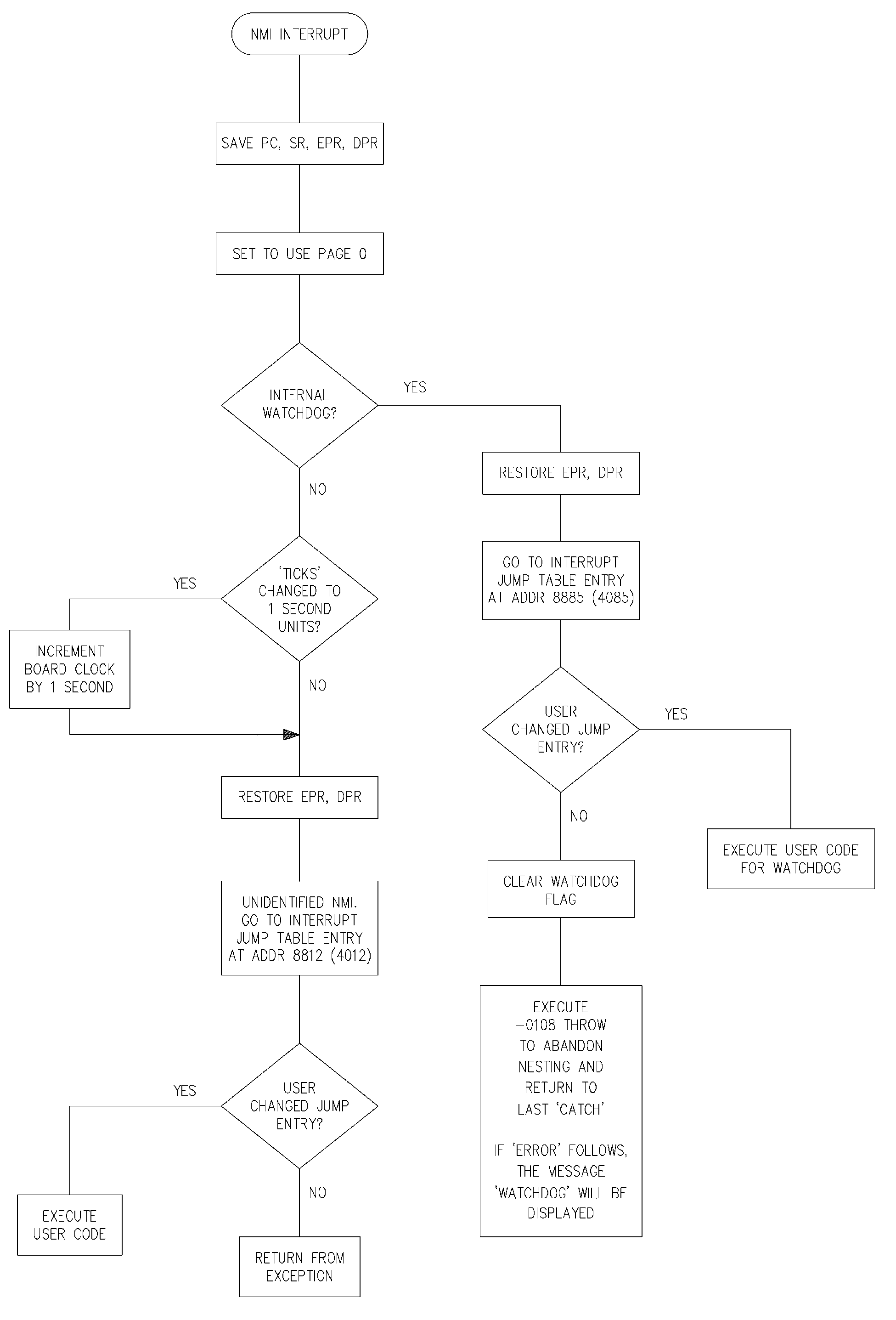
NMI flow diagram This is considered separately because
q The PCF8583 chip clock alarm output is tied to the NMI input q The NMI is also used to service the internal watchdog
Despite these you can normally arrange to use an NMI interrupt whether in Assembler or Forth. The clock output is open-drain; other NMI lines you may add should also pull down to logic 0 in the same way, to give a wired-OR connection at the NMI input to the microprocessor. The NMI input does not have a Schmitt trigger circuit and slow rise-times can give rise to spurious interrupts. If you suspect this either add such a circuit externally or lower the value of the 100k pull-up on the TDS2020F by connecting an external 3k3 resistor between the NMI pin and +5VOUT (pins a26 and z18). The flow diagram shows what happens. At entry address 8885 in the Interrupt Jump Table you can put a jump to your own internal watchdog service routine; at 8812 put one that will respond to your own NMI input. By default there is a 1 second square wave on NMI coming from the chip clock. By assigning your own routine at Interrupt Jump Table address 8812 you will get a task done regularly every second with good accuracy which can be made precise by the time trimmer. For other external NMI interrupts include this code to disable the one-second pulses:
INTERRUPTS USING ASSEMBLY LANGUAGEThe Forth system ROM contains vectors to internal RAM at which you can put your own jump table. There are three bytes each to hold machine-code jump instructions. See the full INTERRUPT JUMP TABLE, page 170. This table is at the start of the user's Flash-EEPROM area before the application program. It is instructive to look at this area in a TDS2020F after power-up. HEX 8800 20 DUMP gives:
8800 A A A 10 1E 68 A A A A A A
10 0 30 A The jump table is mainly preset to 0A, which is the Return From Exception (i.e. interrupt) RTE instruction. Four interrupt jumps are pre-configured and these are marked in the Interrupt Jump Table. We can see two of them in the above memory dump. Each jump has three bytes. The first is 10 and the next two give the absolute address that will be jumped to when the interrupt occurs. When setting the jump table you must make sure that this address will start a string of machine code and that eventually an RTE instruction will cause a return from interrupt. The word ASSIGN fills in the jump table entry (see below) but it is up to you to correctly write the assembler code of the interrupt and to end it with RTE, . The four preset interrupts are Invalid Instruction, Address Error, Free-running Overflow Interrupt B of Timer 3 and the Internal Watchdog. You are free to set up the jump table including reassignment of these four. Next is an example of an interrupt routine written in assembler. This also shows the use of the in-built assembler. If in difficulty with an interrupt written in assembler, see if it is possible to start with the example below and then change it to meet your needs.
\ #ASTIMER.TDS Example of interrupt written in \ assembly language. The internal timer 3, address \ FFB2, and the 16-bit variable %TIMER together form \ a 32-bit counter incrementing every 814ns. Total \ cycle time about 58 minutes. VARIABLE %TIMER \ A 16-bit extension of timer 3
CODE +TIME \ Interrupting word which increments %TIMER B $FFB1 )) 4 ## BNOTI, \ clear timer 3 \ overflow flag. Note the need to both \ READ and then WRITE back with a zero. \ Reading alone is not sufficient %TIMER )) INC, \ increment variable RTE, \ return from interrupt
-24 +ORIGIN ASSIGN +TIME \ timer 3 overflow \ interrupt table entry
: INITIALISE ( - ) \ Set up for interrupts DIS \ disable interrupts $FFB0 4 ONE \ enable overflow interrupt $FFF2 C@ $8F AND \ clear priority of this group $70 OR $FFF2 C! \ set group to priority 7 0 %TIMER ! 0 $FFB2 ! \ clear timer EIS ; \ general interrupt enable
: TIMER-TEST ( - ) \ To demonstrate the extended timer INITIALISE CR BEGIN $FFB2 @ %TIMER @ \ -- double word time 20 D.R 100 MS \ print 10 times per second KEY? \ stop on any key UNTIL KEY DROP ; \ throw away keystroke
To let an interrupt happen several conditions must be fulfilled:
q The priority of the interrupt group in question must be higher than that set in the status register by PRIORITY . In the example the interrupt group priority is set to 7 by the masking and or-ing operations. The status register is set to priority 0 by EIS , the same as 0 PRIORITY . q The particular interrupt must be enabled, setting bit 4 of address $FFB0 does this in the above. Note how useful the words ONE and ZERO are for manipulating bits in the registers.
The -24 +ORIGIN before ASSIGN calculates the interrupt address. The number is taken from the Interrupt Jump Table and this particular code returns hex 886C. ASSIGN fills in the Interrupt Jump Table entry with a jump (hex 10) at address hex 886C and an address to jump to at 886D & 886E. The address will be the body of the word +TIME , which is the start of the assembler code in that word. ASSIGN is 'smart' and knows this is an assembler interrupt. It does more for a high level interrupt. INTERRUPTS WRITTEN IN HIGH-LEVEL FORTHTo clearly show the difference between interrupts in assembly language and Forth, the same example above is now coded in Forth:
\ #HITIMER.TDS Interrupt written in Forth VARIABLE %TIMER \ a 16-bit extension of timer 3
: +TIME \ Interrupting word which increments %TIMER $FFB1 4 ZERO \ clear timer 3 \ overflow flag. Note the need to both \ READ and then WRITE back with a zero. \ Reading alone is not sufficient 1 %TIMER +! \ increment variable RETURN; \ return from interrupt
-24 +ORIGIN ASSIGN +TIME \ timer 3 overflow \ interrupt table entry
: INITIALISE ( - ) \ Set up for interrupts DIS \ disable interrupts $FFB0 4 ONE \ enable overflow interrupt $FFF2 C@ $8F AND \ clear priority of this group $70 OR $FFF2 C! \ set group to priority 7 %TIMER OFF $FFB2 OFF \ clear timer EIS ; \ general interrupt enable
: TIMER-TEST ( - ) \ To demonstrate the extended timer INITIALISE CR BEGIN $FFB2 @ %TIMER @ \ -- double word time 20 D.R 100 MS \ print 10 times per second KEY? \ stop on any key UNTIL KEY DROP ; \ throw away keystroke
This is easy as we saw in the example at the beginning of this section because the words ASSIGN and RETURN; do all the work for you. To create an interrupt in high-level Forth:
q Write the interrupt routine as a normal Forth word and debug it. q
Now change the semicolon to RETURN; so that it has this form: q Use ASSIGN to set up the interrupt. q Create an initialising word that both (i) sets the required priority for the interrupt and (ii) enables it.
When the interrupting word is in high-level Forth, the word ASSIGN works by compiling a headerless word that saves Forth 'registers' on the stack. A new return stack base is then allocated in the free space above the old one. The execution token of the interrupting Forth word is put in the Interpreter Pointer (Register 5) of the Forth inner interpreter and we jump back to Forth. A completely 'new' Forth system has now been created for the duration of the interrupt. ASSIGN also sets the entry in the interrupt jump table. The return from interrupt performed by RETURN; is simpler, we just pull all the old data back off the stack and replace it in the Forth 'registers' before executing a return from interrupt instruction (RTE) which puts us back in the original Forth system exactly where we left it. |
 |
|